Main page
Home bs0dd.net
News
Guest book
Exclusive projects
Phones
List of modelsFirmware
Net Monitor
FT/NM activationNet Monitor (DCT3)
Net Monitor (DCT4)
Soft and games
Java MIDletsOfficial soft
Soft for 5510
PC software
Connectivity
Data-CablesFLOSYS FBUS/MBUS docs
DLR-3 MBUS (atrox)
Modding
Color display (6310)Soft for DCT3 modding
WAP
WAP-gatewayWAP-page
Other
Nokia 9210 archiveElektronika MK
Kannel for Windows
Nokia Net Monitor description (DCT3)
MAIN PAGE
< PREVIOUS PAGE
NEXT PAGE >
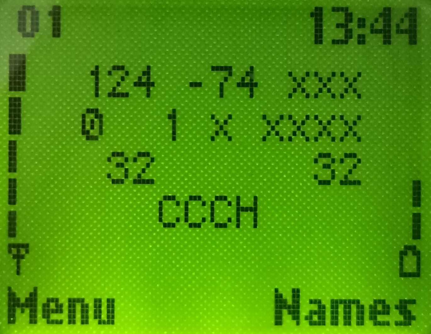
Test 01 – Serving Cell Information (1)
Available in: 2100, 3330, 5110, 6150, 6210, 7110, 8210, 8250
This test displays information about signal, selection characteristics and communication with the serving BTS. It is continued in “Test 02 – Serving Cell Information (2)”.
| Test screen | Help screen |
 |
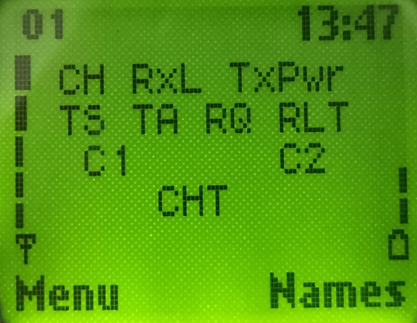 |
CH: Serving cell’s radio frequency channel. In idle mode, this displays the channel of the BCCH carrier. In dedicated mode, this displays the channel the MS is using for communication. This may be preceded by a ‘H’ to indicate frequency hopping in dedicated mode. The display will cycle through the channels being hopped. The radio frequency channel’s number also indicates what band it is in. See below. [GSM 05.05:2.x]
RxL: Received signal strength of the serving cell in dBm. If the value is less than -100dBm, the ‘-’ sign will not be displayed. [GSM 05.08:8.1]
TxPwr: This value displays the output power of the transmitter. A ‘*’ character precedes this value if the transmitter is active (which it always is if this value is displayed). If the transmitter is not active, “xxx” is displayed. [GSM 05.05:4.1.1] The meaning of the values are detailed below. ??comment on Test 45??
TS: The current radio timeslot. When idle, this value displays the timeslot containing the CCCH/BCCH (always 0), otherwise, in dedicated mode a value from 0-7 indicating timeslot for communication. [GSM:05.02]
TA: The timing advance value, used by the MS to tell how early to send bursts (packets) so that they arrive in time and don’t overwrite somebody else’s timeslot. Units are in symbol-periods, which are 3.69 microseconds. This parameter can allow you to calculate your approximate distance to the BTS. Maximum value is 63 (35km), except for GSM400, which is 219. Since the timing advance can only be calculated after a transmission with the network, in idle mode you will need to update it by initiating a transmission, such as quickly starting a call and hanging up. [GSM:05.10]
RQ: The RXQUAL_SUB value. This value, when the phone is communicating with the BTS, shows the received signal quality, calculated from the Bit Error Rate (BER). RXQUAL_SUB differs from RXQUAL, it is used in DTX mode and calculated over a lesser number of frames. It displays ‘x’ when in idle mode. The RXQUAL_SUB value ranges from 0 to 7, where 0 shows the least errors (BER < 0.2%) and 7 shows the most errors (BER > 12.8%). The higher the value, the poorer quality signal and the more likely communication will fail. This value is only displayed in dedicated mode (since it only applies there). The meaning of the values is detailed below. [GSM 05.08:8.2.4]
RLT: The Radio Link Timeout value. This value controls whether the connection will be abandoned. It starts at a value assigned by the network (on BCCH), and is decreased by 1 every time an SACCH message is incorrectly decoded (corrupt), and increased by 2 every time an SACCH message is correctly decoded (intact). The counter never exceeds the initial value, and if the counter reaches 0, the connection is terminated. The maximum initial value of the counter is 64, and the minimum is 4, and is a multiple of 4. SACCH message are sent/received usually about 2 times a second (half each 51-multiframe, which is about 235ms).This value is only displayed in dedicated mode (since it only applies there). [GSM 05.08:5.2]
C1: C1 value (path loss criterion). The C1 value is calculated primarily based on signal strength, but also transmitter capability. This value is used to decide whether a cell is suitable to camp on in idle mode. It is also used in the calculation of C2 values, if supported (see “Test 07 – Current Cell Flags”). If the C1 value falls below 0, cell reselection takes place. C1 value is between -99 and 999. [GSM 05.08:6.4, 6.6.2]
C2: C2 value (reselection criterion). This is used to determine whether to select a new cell for camping on. If a cell’s C2 value is higher than the current cell’s C2 value for at least 5 seconds, the new cell is usually chosen. If C2 values are not supported (see “Test 07 – Current Cell Flags”) or the phone is in dedicated mode, the C1 value is displayed. [GSM 05.08:6.4, 6.6.2]
CHT: The type of logical channel or sub channel or codec/data rate the phone is currently using. See below for an overview. [GSM 04.03, GSM 05.02]
The GSM bands are (Tx and Rx relative to MS):
| Channel | Band | Tx frequency (MHz) | Rx frequency (MHz) |
| 1-124 | GSM900, E-GSM900, R-GSM900 | 890+0.2*ch | 935+0.2*ch |
| 512-885 | GSM1800 | 1710 +0.2*(ch-511) | 1805+0.2*(ch-511) |
| 975-1023 | E-GSM 900, R-GSM900 | 890+0.2*(ch-1023) | 935+0.2*(ch-1023) |
| 0 | E-GSM 900, R-GSM900 | 890 | 935 |
| 955-974 | R-GSM900 | 890+0.2*(ch-1023) | 935+0.2*(ch-1023) |
It can be seen that GSM900 band is contained within E-GSM band, which in turn is contained within R-GSM band. If you are not sure which bands your phone supports you can always test them with “Test 17 – BTS Test”. If the channels are invalid, the test will display “CH: xxxx” and fail. For example, the 8210 supports GSM900, GSM1800 and E-GSM.
The Tx Power Level values are:
| TX (GSM <=900) | 16 | 15 | 14 | 13 | 12 | 11 | 10 | 9 | ||||||||
| TX (GSM 1800) | 9 | 8 | 7 | 6 | 5 | 4 | 3 | 2 | ||||||||
| dBm | 11 | 12 | 13 | 14 | 15 | 16 | 17 | 18 | 19 | 20 | 21 | 22 | 23 | 24 | 25 | 26 |
| Watts | 0,012 | 0,016 | 0,02 | 0,025 | 0,032 | 0,04 | 0,05 | 0,063 | 0,079 | 0,1 | 0,125 | 0,158 | 0,2 | 0,251 | 0,316 | 0,398 |
| TX (GSM <=900) | 8 | 7 | 6 | 5 | 4 | 3 | 2-0 | ||||||||||
| TX (GSM 1800) | 1 | 0 | 31 | 30 | 29 | ||||||||||||
| dBm | 27 | 28 | 29 | 30 | 31 | 32 | 33 | 34 | 35 | 36 | 37 | 38 | 39 | 40 | 41 | 42 | 43 |
| Watts | 0,501 | 0,631 | 0,794 | 1 | 1,26 | 1,58 | 2 | 2,51 | 3,16 | 3,98 | 5 | 6,31 | 8 | 10 | 12 | 15,8 | 20 |
[GSM 05.05:4.1]
The RXQUAL/RXQUAL_SUB values are:
| RXQUAL | Bit Error Rate (BER) (%) |
| 0 | <0.2 |
| 1 | 0.2 – 0.4 |
| 2 | 0.4 – 0.8 |
| 3 | 0.8 – 1.6 |
| 4 | 1.6 – 3.2 |
| 5 | 3.2 – 6.4 |
| 6 | 6.4 – 12.8 |
| 7 | >12.8 |
[GSM 05.08:8.2.4]
RXLev parameter value:
| RX (from) | RX (up to) | RXLev |
| less than | -110 dBm | 0 |
| -110 dBm | -109 dBm | 1 |
| -109 dBm | -108 dBm | 2 |
| ... | ... | ... |
| -49 dBm | -48 dBm | 62 |
| -48 dBm | more | 63 |
Signal strength indicator value on the left side of the display (approximately):
| RX (from - to) | amount of bars |
| from -105 to -100 dBm | 0 |
| from -100 to -95 dBm | 1 |
| from -95 to -90 dBm | 2 |
| from -90 to -85 dBm | 3 |
| more than -85 dBm | 4 |
The valid channel types are:
| Channel Type | Description |
| CCCH | Common Control CHannel. Used for paging and allocating other channels |
| BCCH | Broadcast Control CHannel – Used for broadcasting parameters about the network and Cell Broadcasts |
| CBCH | Common Control CHannel and listening for cell broadcasts on Cell Broadcast CHannel (downlink portion of SDCCH) |
| AGCH | Access Granting CHannel. Sub-channel of the CCCH used for allocating other channels |
| SDCC | SDCCH – Standalone Dedicated Control CHannel – used for sending SMSes, location update, call setup, and other higher-layer tasks |
| SEAR | SEARch – not a channel, but searching for BCCH carriers |
| NSPS | No Serve Power Save mode – not a channel, but sleeping temporarily as a network cannot be found |
| TEFR | Traffic CHannel, for voice using Enhanced Full Rate (EFR) codec |
| TFR | Traffic CHannel, for voice using Full Rate (FR) codec |
| THR0 | Traffic CHannel, for voice using Half Rate (HR) codec on subchannel 0 |
| THR1 | Half Rate Traffic CHannel, for voice using Half Rate (HR) codec on subchannel 1 |
| F144 | Traffic CHannel, for data at 14.4kb/s |
| F96 | Traffic CHannel, for data at 9.6kb/s |
| F72 | Traffic CHannel, for data at 7.2kb/s |
| F48 | Traffic CHannel, for data at 4.8kb/s |
| F24 | Traffic CHannel, for data at 2.4kb/s |
| H480 | Half Rate Traffic CHannel, for data at 4.8kb/s, subchannel 0 |
| H481 | Half Rate Traffic CHannel, for data at 4.8kb/s, subchannel 1 |
| H240 | Half Rate Traffic CHannel, for data at 2.4kb/s, subchannel 0 |
| H241 | Half Rate Traffic CHannel, for data at 2.4kb/s, subchannel 1 |
| FA | FACCH – Fast Associated Control CHannel – subchannel of Traffic CH |
| FAH0 | FACCH – Fast Associated Control CHannel Half Rate, subchannel of Traffic CH, subchannel 0 |
| FAH1 | FACCH – Fast Associated Control CHannel Half Rate, subchannel of Traffic CH, subchannel 1 |
Port: 9201
Переключиться на Русский
Powered by COMPPAG 0.58
2022-2026 © Compys S&N Systems