Main page
Home bs0dd.net
News
Guest book
Exclusive projects
Phones
List of modelsFirmware
Net Monitor
FT/NM activationNet Monitor (DCT3)
Net Monitor (DCT4)
Soft and games
Java MIDletsOfficial soft
Soft for 5510
PC software
Connectivity
Data-CablesFLOSYS FBUS/MBUS docs
DLR-3 MBUS (atrox)
Modding
Color display (6310)Soft for DCT3 modding
WAP
WAP-gatewayWAP-page
Other
Nokia 9210 archiveElektronika MK
Kannel for Windows
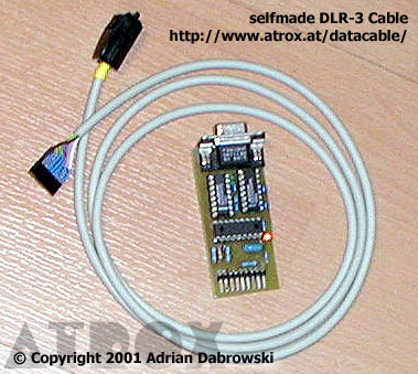
Selfmade Nokia DLR-3P Datacable (atrox)
A thousend thanks to:
- "omolas" probably the first analysis of the DLR-3 cable
- Marcelo Puhl (email only) for sharing his knowladge about MBUS with me.
- N. Hüttisch aka nobbi
These cables has been tested with
- 6210
- 7110
- 3280
- 6160i
- 6162i
- 6161i
- 6185 / 6185i
- 5185i
- 5165i
- 7160
- 7190
THE FIRST VERSION
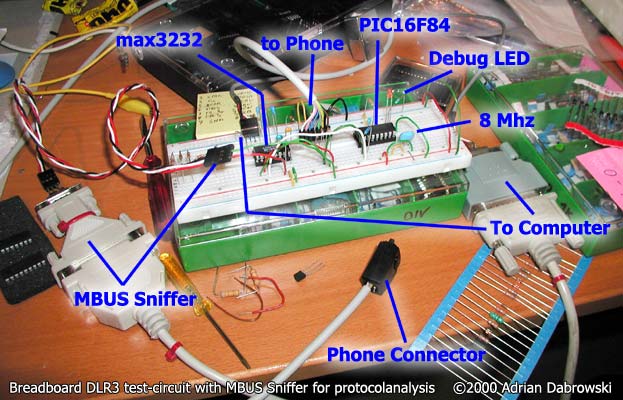
The first Version does not support any flowcontrol but the rest works perfectly. You can make data connections with your favorite Terminal-Program or even surf the Internet, when you disable Hardware-Handshake(RTS/CTS) in the Dialup/Modem-Properties! All you need is:
- 4x 100 nF (ceramic)
- 3x 1K Resistors
- 1x 100 Ohm Resitor
- 1x 15K Resistor
- 1x BAT-41 Schottky-Diode
- 1x 8 Mhz resonator or a 8 Mhz Quarz + 2x 20 pF
- 1x max3232 level-Shifter with charge-pump
- 1x PIC16F84 microprocessor
- 1x Sub-D 9 Connector and a 3 wire Cable
- 1x Phone Connector and a 7 wire Cable
- a HEX-File with the a PIC-program (© Copyright 2001 Adrian Dabrowski)
- The debug-LED with the 1K resistor is optional (heartbeat)
- Description of the phone connector can be found here.
- Description of the Sub-D Connector. Watch out! Pin numbers in the circuit diagram are correct, but the SUBD9-Symbol isn't!
- For a description of the MBUS-Protocol look into the MBUS-Section.
- If you connect RTS and CTS at the Sub-D Connector, this cable will also work with Logomanager.
To get the Phone into the DLR-3 Mode, you must connect XMIC with a 15K Resistor to GND. Then the phone switches on Power (2.8 V @ 6210 or 3.3 V @ 7110) on the SIG-GROUND pin. (Note: In the DAU-9 cable the power was taken from PC's serial port)
Soon the Phone starts sending MBUS-frames to the PIC. If the PIC does not anwser, the Power is switched off after the third frame. After half a second the Power is restored, and the procedure starts again. The Phone communicates with the PIC until the cable gets disconnected from the phone.
If everything is working, the phone accepts AT-Commands on the FBUS pins (19200 and faster, 8N1).
(C) Copyright 2000 Adrian Dabrowski
If you are curios you can look at the test-circuit I used to develop the "first Version"-Cable!
THE SECOND VERSION
|
This version of my data cable supports CTS (so the phone won't be flooded with to much data at once), and DCD because some
programs need this, to work properly. A downside, however, is that you need two max3232 or ADM3202 (or one max3237 which is only available as SMD) As a result this circuit works with the "6210 Cable" Standard-Driver from your Nokia-CD without any changes in the "properties" dialogebox! It also has been tested with Logomanager, PC-BackupRestore, etc. |
 |
- 8x 100 nF (you may like to use 3 more, to decouple each IC)
- 3x 1K Resistors
- 1x 100 Ohm Resitor
- 1x 15K Resistor
- 1x BAT-41 Schottky-Diode
- 1x 4/8 Mhz resonator or a 4/8 Mhz crystal + 2x 20 pF
- 2x max3232 level shifter with charge-pump
- 1x the very popular PIC16F84
- Sockets are recommended.
- 1x Sub-D 9 Connector (female) and a 5 wire Cable
- 1x Phone Connector and a 7 wire Cable
- a HEX-File (8Mhz Version)
(4Mhz Version)(LOST, WANTED) with the PIC-programm
(© Copyright 2001 Adrian Dabrowski) - You can still connect a debug-LED with a 1K resistor to RA2
Warning: Pin numbers of PIC and the Bat41 are overlapping! The correct pin number of RB5 is 11 ! Use of ceramic capacitors will save you troubles with the unusual polarisation.
(C) Copyright 2001 Adrian Dabrowski
THIRD VERSION
The upcomming third Version will support even more!
- CTS signal is important when "uploading" or sending more DATA to the phone than it can send to the GSM-Network. With this signal the Phone can ask the PC to wait until all Data is sent, otherwise data may get lost. (Higher Protocols have their own checksums, and will detect such cases most of the times, but it will nether-the-less slow down the connection) [2nd Version]
- DCD signal; may be important to some Applications, others just ignore it. DCD tells the PC that a data-connection exists. [2nd Version]
- DTR-Drop: This is sometimes used to hang up a connection instead of using "+++ ~1sec~ ath". [New]
- RTS signal got somehow unimportant, because virtually all PCs and Notebooks use bufferd UARTs and are fast enough to handle all data. [2nd Version: static; 3nd Version: dynamic]
- nice circuit diagrams :)
Since the 2nd version is working perfectly with dialup-network, Logomanager and apx. 98% of other Software, do not expect the third circuit end of Jan 2002.
Port: 9201
Переключиться на Русский
Powered by COMPPAG 0.58
2022-2026 © Compys S&N Systems