Main page
Home bs0dd.net
News
Guest book
Exclusive projects
Firmware
Net Monitor (DCT3)
Net Monitor (DCT4)
Official soft
Soft for 5510
PC software
FLOSYS FBUS/MBUS docs
DLR-3 MBUS (atrox)
Soft for DCT3 modding
WAP-page
Elektronika MK
Kannel for Windows
| Schematic for DLR-3 cable | 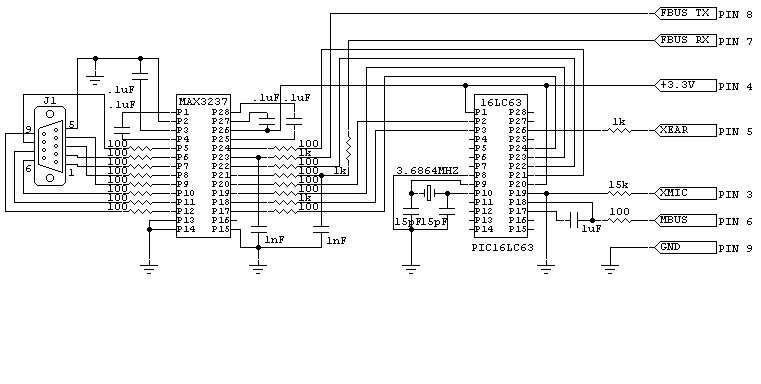 |
If you connect MICIN (pin3) with 15k resistor to logic ground (pin 9), you get 618x phone to show "READY FOR DATA CALL" message and after that it shows "DATA CONNECTION ENDED". When you short pin3 to GND with 15k resistor, phone switches pin4 (what is normally SIGNAL GROUND) to be +3V source for microprocessor, what is embedded in to the cable. After this phone sends (1F/48/00/4E/00/02/01/02/xx/check sum) message to micro (serial settings are 9600Bd, 9bit, odd parity) from MBUS pin (pin6). If you don't acknowledge the phone, then your connection is canceled with "DATA CONNECTION ENDED" message. Micro needs to send to the phone "1F/00/48/7F/xx/check sum" message every time when phone sends something to the micro. After this you can communicate with phone using "AT" commands trough the FBUS (pin7 = RXDATA, pin8 = TXDATA, 19200Bd, 8bit, no parity). There is more things going on in MBUS (like data flow control codes and much more), but this can give you a good kick start. If you use 1k - 10k resistor, phone goes to the "headset" mode, with 20k - 30k phone goes to the "test mode".
| 61XX pins | 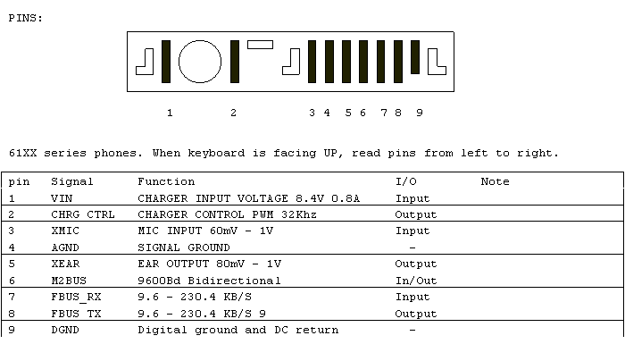 |
Port: 9201
Переключиться на Русский
Powered by COMPPAG 0.58
2022-2026 © Compys S&N Systems